
InnerSoft CAD
Win32 and 64, EnglishGeneral Usage Instructions
InnerSoft CAD is a plug-in for AutoCAD that installs a set of productivity tools.
Once you install the plug-in, InnerSoft adds a Ribbon Tab, a Drop-down Menu and a Toolbar to the AutoCAD menu collection.
Screenshots


Commands
| Ribbon/Toolbar Icon | Command | Command Description |
|---|---|---|

|
IniciarCopiaACapa |
A window with a combo box allows the user to select one of the existing drawing layers. Then the user must select a set of objects on the drawing screen. Finally, all the objects will be COPIED to the selected layer. You can also copy objects to a collection of layers. For this purpose, the user must select a set of objects from AutoCAD: the application will list the layers to which these objects belong. Objects will be copied to all these layers. This tool works in paper or model space. |

|
IniciarTransformacion |
You can convert to a 3D-Polyline a set with the following objects: Lines, 2D-Polylines, LW-Polylines, SP-Lines, MLines, 3DFaces, Polyface Meshes, Polygon Meshes, and 2D Solids. Covert to Point the vertex of a set with the following objects: Lines, 2D-Polylines, LW-Polylines, 3D-Polylines SP-Lines, MLines, 3DFaces, Polyface Meshes, Polygon Meshes, 2D Solids, Arc, Centers, Circle Centers, Ellipse Centers. Covert multiple selections of objects to blocks. Convert Splines to Polylines. |

|
IniciarDescartarRepetidos |
Select a set of points. All not duplicated points (same X and Y coordinates) will be copied to a layer named: InnerSoft-FilteredPoints. |

|
IniciarMallar |
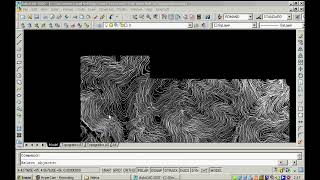
This tool creates a polygonal mesh from vertexes of the following objects: polylines, LW-Polylines, 3D-Polylines, and lines. The user must input the mesh density of axis X and axis Y (a number between 2 and 256). The application will ask for an object selection, lower right corner, and upper left corner of mesh. Then it will create terrain sections from vertical sections defined by every axis (vertical and horizontal axis inside the corners). |

|
IniciarGirarTodo |
Rotate a selection of objects a certain amount around a particular point of each object. This function does not set the angle of the object relative to the horizontal axis (value often appearing in the properties of the object), but a specified amount from this original angle – clockwise or anticlockwise-. Therefore, if you rotate 30 degrees an object that already has an angle of 45 from the X axis, its final angle is 75 degrees from the X axis. The usefulness of this tool is to rotate a certain amount of a set of objects that have different rotations (have not a common angle from the X axis) or rotate a set of objects a certain amount around their internal points (do not rotate around the same base point). The angle must be introduced in degrees (circumference divided into 360 degrees). You can rotate each object around the center of its bounding box, or around its insertion point or first vertex. |

|
IniciarBorrarCapas |
First, get a selection of objects on the AutoCAD screen. The app will create the list of layers to which these objects belong; i.e. the layers to be emptied are defined from any object contained therein. All objects for each of these layers will be deleted. Finally, the application asks if the user wants to delete the layers that have been emptied. |

|
IniciarTriangulacion |
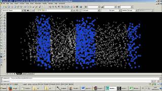
This command uses Delaunay Triangulation Method for a cloud of points. User must choose if triangulation includes the drawing of 3D-Faces, lines, or both (drawing resulting lines take more time than drawing resulting 3D-Faces). During the execution, the cloud of points will be checked to reject duplicated points: those that have the same X and Y coordinates. The application will not control the circumscribed radium of the triangles. |

|
IniciarCopiaADibujo |
This tool copies a set of objects to the rest of the opening drawings. In a window form, you must select if you will copy the set of objects to the paper or model space. Also can choose if paste the selected objects as a block or not. |

|
IniciarProyectarTodo |
The user must set a number as a Z coordinate from the menu. The app will ask for an object’s selection on the AutoCAD screen. Every object in selection will be geometrically projected onto the X-Y plane at user input Z-Coordinate. Some types of objects cannot be projected, but can be flattened -set the normal vector of those objects as (0, 0, 1)-. All those planar polylines (LW and 2D) that have been 3D rotated with respect to the X or Y axis, will not be projected because of their arcs (arcs should be projected as ellipses, and AutoCAD does not allow polylines with ellipses). Anyway, you can always explode them and project their segments and arcs separately. Users can project the original object or a copy of the object (original objects can be copied to layer "InnerSoft-Projection" or can be copied to a new drawing). |

|
IniciarGestorK |
The basic function of the manager is in detailing how many times a block is inserted in your drawing (detailed by its layer and insertion point) and extracting block definitions in AutoCAD individual files (each block definition in a single file). |

|
IniciarEdicion3DPoly |
The purpose of this tool is to modify the coordinates of a 3D polyline using its table of coordinates. There are three ways to populate the table: • Select an existing polyline in AutoCAD; press the Get 3DPOLY button. • Manually input coordinates in the table. • Paste in the table a list of coordinates, which can be previously available in, for instance, an Excel spreadsheet. Press the Update 3DPOLY button to draw the polyline in AutoCAD or update it according to the data in the table. By checking the Automatic Update option, any changes that you make in the table will be automatically reflected in AutoCAD. The tool does not detect changes in the polyline that are made directly in AutoCAD. If you make any change in the polyline directly in AutoCAD, press the Get 3DPOLY button and select the polyline in order to update the table of coordinates. Once the table is populated, you can modify the data by direct input, or by copying and pasting or inserting the values. |

|
IniciarCopiaM |
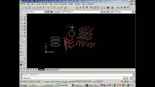
This tool is used to copy an object and insert it into the characteristic points of a selection of objects. You must take first multiple selections of objects in which vertices/insertion points/centers want to insert the object. This is done from the "Add Insertion Points" button. Then select the object from the "Select Object to Copy ' button. Finally, click the 'Copy' button to insert the object in the characteristic points of the first selection of objects. In the tabs above you have all the types of AutoCAD objects on whose characteristic points can insert the object. For each object type, there are checkboxes that allow you to check the characteristic points where you want to insert the object. For instance, we can insert the object in the start point, end point, or midpoint of all selected lines. The collection of insertion points may be formed in several steps. |

|
IniciarCruces |
This tool inserts a grid of crosses defined by X and Y intervals. Intervals must be positive integer values. Also can choose if a text with the (X, Y) coordinates values are inserted for each cross. |

|
IniciarDivideGradua |
This tool works as the Divide/Measure commands of AutoCAD. The difference is that this AutoCAD commands needs an object; this InnerSoft tool needs only two points that you must get on AutoCAD model space. Then the application divides/measures the segment that joins them. You can insert a cumulative index for each division point. |

|
IniciarGestorH |
List all invisible objects. Turn visible/invisible a selection of objects. |

|
IniciarModificarTextos |
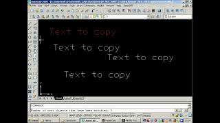
There are two different tools available on this menu. In the first tab, named Prefix/Suffix, you can enter a prefix, a suffix, or both. Press Select Texts to enter a selection of AutoCAD text objects (Texts or MTexts). The suffix or prefix will be added to each selected text. In the second tab, named Equate Texts, you can equate the string of a selection of texts to the string of a singular text. First, you must press the button Select Text To Copy. Its text string will be the text reference. Then press the button Select Texts to enter a selection of text objects in AutoCAD (as many as you want). Finally, the application will set the reference text as the text string of all these text objects. Therefore, application equates the content of a selection of texts to a reference text. |

|
IniciarExportarAlin |
Export data of an axis formed by joined lines and arcs. |

|
IniciarNumerar |
This tool can be used to sort and index a set of objects by natural numbers, inserting a cumulative numerical index near them. Users can set the sort order with respect to the coordinate axis X or axis Y; according to a direction for the axis: • Up: lowest to the highest value of X or Y coordinate. • Down: highest to the lowest value of X or Y coordinate. Users can also sort by Order of Selection, so the indexes will be assigned in the same order that was used when selecting objects on the AutoCAD model space. There are options to choose the insertion point of the index text object (first vertex or center of the object versus the center of the box containing the object), angle and obliquity of the text, as well as the prefix that will precede each index. You can also choose the first index from which to start numbering (must be a positive integer). |

|
IniciarVolumenMalla |
This menu has three different methods to compute the volume of a triangulated 3DFace mesh. Volume is computed from a Z plane located in the lower vertex of all 3DFaces vertexes. |

|
IniciarExportacion |
You can export to Excel object's properties such as length, projected length, area or volume. You can also export the vertex coordinates of a set of AutoCAD objects such as lines, polylines, points, mesh... |

|
IniciarImportacion |
You can import the vertex coordinates of a set of 2D/3D polylines from an Excel Sheet. There are 3 different methods of importation. You can also import a set of points from Excel defined by (X, Y) coordinates or (X, Y, Z) coordinates. Also, you are able to import a set of texts with an insertion point for each one. |

|
IniciarConsulta |
You can get the total sum of areas or total sum of lengths of a set of objects. You can choose between three selection methods (on screen, by layer or entire drawing). You can also filter the selection by object types. Additionally you can also get the total sum of a path composed of points that you get on screen. |

|
IniciarAyuda |
Open the PDF Help File. |

|
IniciarExtendedSelect |
This tool works similarly to the Quick Selection tool of AutoCAD. Its peculiarity is that it's focused on the selection of points, and can accumulate various geometric conditions for its three coordinates: X, Y, and Z. It also allows applying different actions to the resulting selection of points. The menu has three tables to apply filters on each of the three coordinates of the points. Each of these tables accepts one, several, or no intervals. Selected points are those that meet the geometrical conditions of the three tables. I.e., those whose X coordinate belongs to any of the intervals added to the X Filter table, and also its Y coordinate belongs to any of the intervals added to the Y Filter table, and also its Z coordinate belongs to any of the intervals added to Z Filter table. If you do not want to apply any restrictions on any of the coordinates, do not enter any interval in its table. |

|
IniciarGestorG |
Budgets and Measurements Manager consists of a tree on the left, which list and organized the chapters and items of each chapter. At the center is the table, which lists measurements of each item, computing the total sum of different columns. Measurements are length or area values get from AutoCAD objects, user inputs, and elevation of vertices. |

|
IniciarAcotarTodo |
You can dimension multiple selections of objects. On the tabs above you can choose the dimension type for every type of AutoCAD object: aligned, linear, angular, radius, diameter, or arc length. The objects allowed are Line, 3D-Polyline, 2D-Polyline, LW-Polyline, Arch, Circle, Region, Hatch, and Block Insertion. For Region, Hatch, and Block Insertion you can only dimension its bounding box. The setting for these objects is on the Others tab. The configuration on the Arches tab applies to simple arches or any arches in any polyline. The configuration on the Segments tab applies to simple lines or any straight lines in a polyline. |

|
IniciarContadores |
Count equal texts or equal blocks to a pattern. Also, identify and draw all defined blocks in the Drawing. Near every block, will show its name and number of insertions (excluding listed insertions). |

|
IniciarEscalaArea |
You can select any of these objects (only one object): LWPolyline, Circle, Region, Ellipse, Arc, Hatch, Polyline, and/or Spline. Then a window will show the area of this object. In this window, you must input the numeric value of the new area for this object. Once the object is scaled, the app will send to the command line the scale factor used in the operation. |

|
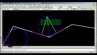
IniciarPerfil |
The command will draw the longitudinal profile of a surface from an alignment. The surface may be composed of Lines, SPlines, 3D polylines, Arcs, Ellipses, Circles, triangular 3DFaces or planar quadrangular 3DFaces, planar 2D polylines, or planar LW polylines. These elements must have an elevation or height in AutoCAD (a 3D terrain). |

|
IniciarAplanarTodo |
Set the normal vector of the object as (0, 0, 1). Working with entities: Arc, Attribute, Attribute Reference, Block Reference, Circle, Dimension, External Reference, Hatch, Leader, LW-Polyline, Line, MInsertBlock, MText, Point, Region, Section, Shape, Solid, Text, Tolerance, and Trace Ellipses are excluded. |

|
IniciarGrafica |
Join multiple selections of points drawing a 3D-Polyline. Draw several Regression objects from a set of points: 2D line, 3D line, 3D sphere, 2D circle, and 3D plane. Draw a 2D & 3D convex hull from a set of points. Draw clothoid, parabolas, circular transition curves, Wholly Transitional Curves, clothoid transition curves, and parabolic vertical transitions. |

|
IniciarImportarPerfil |
This tool creates the longitudinal profile of Point Cloud data from Excel. That is, it creates a longitudinal profile by consecutively joining the points that it reads from the Excel sheet. You can also draw the points in three dimensions by joining them using a polyline. |

|
IniciarCatenariaPro |
Draw a Catenary by 3 points. Draw a Catenary by Vertex is the lowest point. Draw a Catenary by Two Points and Sag at the Left. Draw a Catenary by Two Points and Sag at the Right. Draw a Catenary by Two Points and Vertical Deflection. |

|
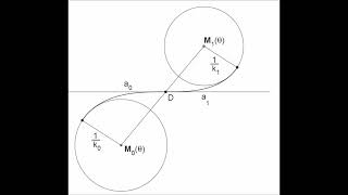
IniciarClotoidePro |
Draw A single clothoid from a straight line to a circle. A pair of clothoid from circle to circle forms an S-curve. A pair of clothoid from circle to circle forms a C-curve. |

|
IniciarLevel |
This InnerSoft CAD tool lets you insert ground-level marks automatically. We must first select the baseline. Next, we select the points where we want the dimension. The tool inserts a point, plus a block with the level symbol, plus a text with the perpendicular distance from the point to the baseline. The baseline can be in any orientation, and the symbols will be aligned with respect to that line. If we move the symbols and execute the REGEN command, the dimension will update, showing the new distance. Keep in mind that this dimension is calculated with respect to the point, not with respect to the block or with respect to the text. |

|
IniciarR |
Open the window to activate the product. |

|
VideoHelp |
Go to video help web. |

|
BuyInnerSoft |
Get a license for the FULL version. |
Installation/Uninstallation
The installer that ran when you downloaded this app/plug-in from Autodesk App Store will start installing the app/plug-in. OR, simply double-click the downloaded installer to install the app/plugin. You may need to restart the Autodesk product to activate the app/plug-in. To uninstall this plug-in, exit the Autodesk product if you are currently running it, simply rerun the installer, and select the "Uninstall" button. OR, click Control Panel > Programs > Programs and Features (Windows 7/8.1/10/11) and uninstall as you would any other application from your system.
Additional Information
This plug-in works as a limited trial version.
You can use for free: • General Panel: Partially available for free: You can use tools Inquiry and Objects Converter. • Survey Panel: Partially available for free: You can use buttons ‘Compute Section’ and ‘Draw Auxiliary View’ from the Longitudinal Profile tool. • Modify Panel: Partially available for free: You can use tools Flatten All, Modify Texts, and Scale by Area. • Managers Panel: Partially available for free: Budgets and Measurements Manager: Partially available for free: You cannot open or save Project files, export data to Excel, remove or create new Items or Chapters. CAD Library Manager: Partially available for free: You cannot open or save Project files, create new books or libraries or delete them. Blocks Manager: Partially available for free: You cannot open or save Project files, export data to Excel, or extract or insert block definitions. Hidden Manager: Fully available for free. • Miscellaneous Panel: Partially available for free: you can use everything but the Geometric Tools.
Known Issues
You may have to login to Windows as Administrator or have to modify User Account Control in order to activate successfully InnerSoft CAD and use the FULL VERSION.
Contact
Author/Company Information
Support Information
Email: innersoft@itspanish.org
Website: http://innersoft.itspanish.org/en/
Version History
| Version Number | Version Description |
|---|---|
|
4.6 |
The security system is more stable. |
|
4.5.1 |
Fixed some minor Menu related issues |
|
4.5.0 |
Added support for AutoCAD 2023 |
|
4.5 |
Added Auto Symbol Level tool. |
|
4.3.1 |
Added support for AutoCAD 2022. |
|
4.1.0 |
Added support for AutoCAD 2020 |
|
4.0.0 |
Added new command Draw Catenary Pro, for drawing a catenary by maximum deflection, by sag at point, by three points |
|
3.9.0 |
Added support for drawing a catenary |
|
3.8.1 |
Added support for Autodesk® AutoCAD® 2018 |
|
3.8.0 |
Added a better presentation for Inquiry menu summary. |
|
3.7.2 |
Added support for AutoCAD® 2017 |
|
3.7.1 |
Added support for AutoCAD® 2016 |
|
3.7.0 |
New tool to draw a catenary in AutoCAD. Catenaries added to Geometric Tools. New tool to edit a 3DPoly using its table of coordinates. |
|
3.4.0 |
Budgets and Measurements Manager has new commands: undo and redo; cut, copy and insert rows; copy and paste cells. Now you can copy cells from Excel and paste them into the Manager (but not vice versa). |
|
3.0.0 |
New tools in Geometric Tools Menu: Clothoid transition curves and Wholly Transitional Curves. |
|
2.9.0 |
New tools in Geometric Tools Menu: regression tools to draw 3D lines, 3D planes, 2D circles and 3D spheres from a set of points; new tool to draw a 3D convex hull from a set of points. Budgets and Measurements Manager now have multiplier columns for Items Table and Chapters Table. |
|
2.8.0 |
New tools in Geometric Tools Menu: regression tools to draw 3D lines, 3D planes, 2D circles and 3D spheres from a set of points; new tool to draw a 3D convex hull from a set of points. Budgets and Measurements Manager now have multiplier columns for Items Table and Chapters Table. |
|
2.7.1 |
Updated for compatibility with AutoCAD® 2013 and Minor bug fixes. |
|
2.6.0 |
Few files are updated. |
|
2.5.0 |
Items of Measurements Manager now can get measurements from multiple AutoCAD Drawings. |
