
Assembly drawings
Win64, EnglishGeneral Usage Instructions
-
Select one or more blocks in the model space. The program can extract blocks from within blocks, and they will also be formatted as assemblies (except for blocks marked as non-explosive).
-
Save the drawing! The command is very long and complex; fatal failures are possible.
-
Call the Assembly Drawings program (AsmDraw command). The button is in the header of the settings tab in the A>V>C> Options Palette.
-
Note that the program will immediately write in the command line which styles of this and other commands will be used.
-
If nothing has been selected in advance, the program will ask you to select assembly blocks. The request will contain command line options for quickly switching the styles of the AsmDraw, Expose, and DimDet commands; as well as the TUNE option to open the settings dialog.
-
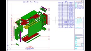
If you have already arranged the assemblies in the model in advance so that they will not block each other in the viewports, you can disable the option to create an Assembly Exhibition. But usually the program itself makes copies of the blocks in the free space of the model space. If you have not specified a drawing template, the program will use the current file as a template.
-
If you have not specified a template sheet or the template drawing does not have a specified sheet, the program will search for a sheet with viewports and display a query - whether this sheet can be used as a template.
-
The program will calculate how many sheets are required to accommodate all the assemblies and make copies of the template sheet. All objects are copied to the new sheets, except for ModelDoc views, leaders, and dimensions.
-
The program will place as many assemblies on the sheet as there are viewports in the template. But if you specified a non-zero number of assemblies per sheet in the settings, the old viewports will be ignore,d and the program will divide the sheet into the specified number of equal parts.
-
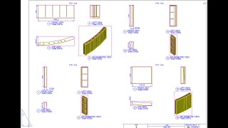
Then the program will start creating drawings on each sheet. Old viewports will be divided into several new viewports proportionally to the size of the assembly, and each of them will contain a view of the assembly from different angles.
-
Orthogonal views are adjusted to one scale and are located strictly opposite each other along the X and Y axes of the paper space. You can also set up all sheet assemblies to be printed in one scale.
-
Three assembly dimensions are placed on two specified views. Dimension objects are assigned a dimension style from the settings of the Dimensions for Detailing (DimDet) program, and if the style is not specified there, the current one is taken. Insist on the dimension style with the _DimStyle command. In any case, the program will disable the creation of dimensions on an additional callout, since this always leads to the imposition of numbers on another view.
-
Callouts with part numbers are placed on the specified view (usually on an isometric view). In this view, the program leaves space on the left and right for callouts.
-
If some callouts could not be placed (some parts are invisible, hidden by other parts), then the program tries to place callouts on the views above or below the specified one, where there is also space left on the left and right. But if the details are not visible there either, the program will try to place callouts on all views without sorting. And in this case, the callouts will definitely be superimposed on the neighboring views.
-
The settings for placing callouts and the substitution template are in the settings of the Place Leaders command. And the style of the Multi-leader itself can be adjusted using the _MLeaderStyle command. There, you can also select MLeaders with blocks at the end, including "number in circle" = "bubble".
-
In the Place Leaders command, you can enable the option to create a text listing of invisible parts (parts that couldn't be called out). There's no room for this text in the drawing, so the program will place it directly in the center of the view on a non-printing layer. Use this text only as a warning.
-
The program will find all blocks in the sheet space (which are copied from the sheet template), and look for variable (not constant) attributes in them. You can configure which attributes to insert simple texts or calculated fields, or substitutions of viewport and assembly properties.
-
The program can fill in the sheet tables if the style of one of the AVC table commands (except for the Drilling Table) is specified in the first cell of the table.
-
The program may take a long time to run. You can interrupt the work by pressing ESC.
Screenshots


Commands
| Ribbon/Toolbar Icon | Command | Command Description |
|---|---|---|

|
AsmDraw |
Full automation of assembly drawings for all assembly-blocks in 1 click. Copies of assemblies in the model, creation of sheets and viewports, signatures of views, overall dimensions, filling in tables. |
Installation/Uninstallation
The installer that ran when you downloaded this app/plug-in from the Autodesk App Store will start installing the app/plug-in. OR, simply double-click the downloaded installer to install the app/plugin. Make sure that the Autodesk product is completely closed when running the installer.
To uninstall this plug-in, exit the Autodesk product if you are currently running it, simply rerun the installer, and select the "Uninstall" button. OR, click Control Panel > Programs > Programs and Features (Windows 10/11) and uninstall as you would any other application from your system.
Additional Information
Known Issues
The Assembly Drawings program is designed to work with small assemblies of 10-20 parts. Such as sections of exhibition stand partitions, furniture drawers. Do not try to use the command for huge assemblies and super-assemblies of the entire construction object.
The program works only with assembly blocks. It does not work with individual solids, nor does not work with groups. Use AsmCreate to create assembly blocks.
The program does not work with annotative and non-explosive blocks (they are not considered assemblies).
Although the program adjusts the viewport sizes to the size of the assemblies, you cannot use assemblies directly from the main model. It is necessary to place copies of the assembly blocks away from the main model at such distances that they do not block each other at any angle. To do this, you can enable the option to call the Expose Assemblies command (a separate license is not required). But you must carefully configure this command for optimal distances between assemblies along all axes. And it is still possible that the assemblies will block each other in some views. Check isometric views especially carefully.
Contact
Author/Company Information
Support Information
Support is provided only by e-mail: avc.programming@gmail.com
WhatsApp: A V C Programming
Telegram: @avc_programming
You can ask any questions about the work of A>V>C> programs, their installation and configuration, optimization of the work of engineers, and setting up business processes in the exhibition business. Help is provided to all users, regardless of whether they donated or not. Any suggestions and comments are welcome for further improvement of the programs.
The main method of communication is e-mail. You can write in any language. If you do not write in English, then write in short, simple but complete sentences without abbreviations and special terms.
Do not forget to attach the problem ".DWG" file to the letter.
Version History
| Version Number | Version Description |
|---|---|
|
2024.11.03 |
First public version. |
