
AVC 3D-kit
Win32 and 64, EnglishGeneral Usage Instructions
-
Read the description of each A>V>C> plugin command that you plan to use. Contact technical support only if the description does not provide the answer. It will take a long time to master all the features and correctly configure all the commands. Do not rush to master them all at once. The A>V>C> commands can work almost independently of each other. Master the commands one at a time. To get started, use the default settings and available "styles" for each command.
-
Create a DWG drawing template with the sheets (layouts), layers, materials, blocks, text styles, leader styles, dimensions, and table styles you need. Write this template in the Autodesk® AutoCAD® settings in the template for the _QNew command or in the AvcOptions settings in the main template so that the plugins find the necessary layers and materials.
-
Check that the drawing units are set correctly - millimeters or inches (InsUnits system variable = 4 or 1).
-
Add custom drawing properties to the template to store information about the design item. This is usually a drawing identifier, the names of the participants in the design, the name of the customer, and the product. For the convenience of creating custom drawing properties, use the A>V>C> Properties Palette (AvcPalette) on the Drawing tab.
-
Use blocks with visible non-constant attributes as title blocks on sheets. Fields must be inserted in the attributes that refer to the properties of the given drawing. Then you can fill in the drawing properties once (for example, in the A>V>C> Properties Palette), and this data will appear automatically on all sheets.
-
It is better to store large collections of blocks with which you will designate purchased products or standard assemblies in separate DWG files. When updating such a collection, you can easily update the blocks in the drawings with the Block Update (BUpdate) command.
-
Design a model of your product using 3D solids.
-
It is better to design from the dimensional box, peeling the parts with the AVC Slice (ASL) and Multi-Slice (MSL) commands.
-
You can split the overall box into sections using one of the Chop and Chop Edge commands (Ch, ChE).
-
We also arrange the ribs using the Chop commands with the Ribs option enabled.
-
The grooves and dadoes are made with the Dado Joint Command (DDJ).
-
The cruciform joints are made with the command Cross-Piece (CRS).
-
To subtract solids with clearance, use the Gap (GAP) command.
-
-
Prepare blocks for all purchased items.
-
Inside these blocks, place solids of the Hole layer, so that the Drill (DRI) command will work later.
-
For fasteners, you need to prepare blocks suitable for the Fixture command. It is important to correctly orient the solids inside such a block and set up all the placement attributes.
-
Blocks can be measured with the BlockMetric command so that it has the attributes of size, weight, and price.
-
Then, in the Properties Palette A>V>C> (AvcPalette), lock the measurement and enter the correct weight and price for all these items.
-
Remove the Explodable label from product blocks so that no other commands work with them as with assemblies, but consider them as ready-made, purchased products.
-
Add the invisible attributes you need to the blocks - catalog, article, and the like. Attributes can be added and removed directly in the Properties Palette A>V>C>. Attributes are useful if you need to extract data, for example, for BIM.
-
-
Arrange fittings and fasteners. For fasteners, use the Fixture command with your blocks (not the ones included in the program). Remove excess fasteners where there are too many of them. Move where they hit the cutouts and on top of each other.
-
Drill all mounting holes (additive) with the Drill (DRI) command.
-
If it turns out that the mounting holes need to be changed, then all holes can be removed with the command Remove Holes (RemHoles).
-
If you have nothing to do, then you can assign each part a text name such as "Shelf", "Rib", and the like. Write it down in the Kind field. But remember, this is a waste of time.
-
Record supporting information about the parts in the Info field. For example, write down what you need to make at the end of the part.
Read more here
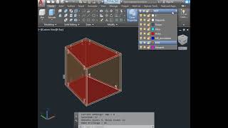
Screenshots


Commands
| Ribbon/Toolbar Icon | Command | Command Description |
|---|---|---|

|
ASU |
Avc Sub. command to drill holes in 3D solids |

|
AutoSnap |
Automatic shutdown of all snaps when creating a text |

|
StSt |
Stair-step. Make stair-step from a flat solid. Orthogonal side-faces |

|
AutoOrtho |
Automatic shutdown orthogonal mode when creating a text |

|
CRS |
Cross-Piece. To make the notches in intersecting parts (3D-solids) to connect cross. |

|
SumArea |
calculates the sum of the areas of all selected drawing objects. |

|
Lay |
Lay 3D-solids to XY plane |

|
ChE |
Chop Edge. Cut a solid into same length pieces along edge |

|
TNT |
Explosion of assembly files. |

|
AVCNum |
Give the names to solids as ordered numbers |

|
ASL |
Avc Slice. Delamination (peeling) flat and curved faces of solid. |

|
Ch |
Chop. Cut 3D details into flat pieces |

|
ALD |
AVC Leader. Enabling and disabling smart leaders, setting up their work. |

|
SSO |
Search for drawing objects similar to the sample without any queries. |

|
DDJ |
Formation of dado joinery between a 2 contacting solids. Automatic creation dadoes, grooves, pockets, cutouts. |

|
PTT |
Paste To Table. Paste text-table data from Windows clipboard to ACAD table |

|
PNo |
Numbering of drawing sheets in one dwg file, without sheet set. Drawing up a table of contents. |

|
SumLen |
calculates the sum of the lengths of all selected drawing objects. |

|
AutoAnn |
Automatic activating of "Annotations" layer to create text, leader, dimension, etc. |

|
SNN |
Select NoName. Find and select object without name |

|
AVCUpdate |
Update all smart leaders in current drawing by one click |

|
Fixture |
Arrangement of fixtures along joints of solids |

|
Miter Joint |
Cutting the solid along the bisector of the angle of joining of two surfaces. |

|
TntUpdate |
Quickly update all blocks with TNT-exploded assembly views. |

|
MultiSlice |
Cutting off many solid surfaces. Creating a Miter joint. Modeling columns and walls from particleboard/plywood in 1 click. |

|
RemHoles |
Find and remove all cylindrical holes in all solid parts, even inside assembly blocks. |

|
TabSlot |
Tab-slot joint |

|
Reduce Weight |
Cut through windows or pockets in free places of the part to reduce its weight. |

|
SSub |
Solid Subtract |
Installation/Uninstallation
Attention! Before installing this set of programs, you must remove all other plugins A>V>C>. To do this, use the standard tools or Remove Programs from the Control Panel.
The installer that was run when you downloaded this app/plugin from the Autodesk App Store will start installing the app/plugin. OR, simply double-click the downloaded installer to install the app/plugin. You may need to restart your Autodesk product to activate the app/plugin. To uninstall this plugin, exit the Autodesk product if you are currently running it, and simply rerun the installer and select the "Uninstall" button. OR click Control Panel > Programs > Programs and Features (Windows 10/11) and uninstall as you would any other system application.
Additional Information
Check out the full list of A>V>C> programs on this site - maybe you can work less and earn more.
Are you missing features or settings? Do you need other commands and programs?
Let's make A>V>C> plugins better.
Let's do it together!
Known Issues
Contact
Author/Company Information
Support Information
Please write your questions and concerns in the comments to the program on this site.
Version History
| Version Number | Version Description |
|---|---|
|
2025.08.02 |
All updates on August 2025: https://sites.google.com/site/avcplugins/changelog |
|
2025.02.01 |
1. DadoJoint & TabSlot: new Backlash option for an additional gap along the slot depth. 2. License management fixed: Activate button error: "Too old version" 3. AvcOptions fixed in AutoCAD 2025: Crash when opening the palette in systems with rare localizations (for example ru-KZ). 4. SolSize: The command now erases materials and colors of solid surfaces if all surfaces were accidentally painted the same color. 5. Fixture: Now start the arrangement in the positive direction of the axes of the UCS (previously the beginning of the joint closest to the beginning of the WCS was selected) 6. Fixture: If you need to mirror fasteners, the program will now mirror the first half of the joint if the Y axis of the fastener is directed in the negative direction to the current coordinate system. This way, you will get a symmetrical arrangement of fasteners on both sides of the shelf. 7. Fixture: In the Fixture.dwg file, asymmetrical fasteners have been adjusted to facilitate mirror installation. 8. Chop fixed: assigning a color to the slices from the material. 9. Substitution %dimensions% fixed: The inch symbol in the architectural drawing unit style was duplicated. 10. Substitutions %weight% and %cost% fixed: now they also work for blocks with metrics, regardless of localization. 11. AvcPalette fixed: Dimensions in feet and inches were not recognized when entering block metrics. 12. AvcPalette fixed: The metric blocked from measurement was not displayed if the volume was zero. 13. Substitution %mat%: The color name is now substituted instead of the Global material only if the part is specified as a catalog color (not index or RGB). 14. SmartLeader fixed: Crash when searching for objects in a drawing with broken external references. |
|
2024.09.04 |
Solid metric: the procedure for reducing the size of a part by the thickness of the edge bandings now works not only with 4-sided parts. But only the thickness of the edges directed strictly along X and Y are still subtracted. AvcPalette: Added an option to disable all ordinary properties at once. It makes the palette as compact as possible. LAY & Solid Metric: Now works with round pipes if they are assigned a material of the "Rod" type. Solid Metric: The length of a round pipe bent along an arc is calculated as the length of the arc along the axis of the torus. And the width and thickness are the minor diameter of the torus. The Sweep property is automatically adjusted. Solid Metric: New technology names added: "Cut pipe", "Processed pipe". Fixture: New "Ignore UCS" option. SweepSize: Added options for the size of unfolded solids: Longer side, Center line, Longer Segments. LAY: New Flip option. Dark theme support: Dark background for form section headers. |
|
2024.03.00 |
Compatible with AutoCAD 2025 |
|
2023.05.02 |
All updates for 2023 May |
|
2020.8.1 |
Added 2022 support (No change in version number). |
|
2020.2 |
- Compatible with Autodesk® AutoCAD® 2021 - Cumulative updates |
|
2019.3.4 |
Compatible with AutoCAD 2020 New activation system Included all updates to all plug-ins for March 2019 |
|
2018.3 |
2018.3 AutoCAD 2019 compatibility New command Fixture Included all updates to all plug-ins for March 2018 |
|
2017.4.0 |
Compatible with Autodesk® AutoCAD® 2018 |
|
2.12 |
Added all new commands. |
|
2.2 |
Smart Leader version updated to 2.3 |
|
2.1 |
All plugins, latest updates, error fixes. |
