
ProSolids Wire EDM
Win64, EnglishGeneral Usage Instructions
The add-in will load under the workspace MANUFACTURE - > WIRE EDM
The interface consists of the toolbar under WIRE EDM, and the ProSolids Browser anchored to the right side of the screen by default.
For additional help you can go to our website here: https://www.ProSolids.com/help
Basic Workflow
- Model the part or open the part file in Autodesk® Fusion®.
- Change to the Manufacture Workspace
- Define the Machine type and machine parameters.
- Define the Stock and Plane definitions and setup.
- Select desired geometry.
- Generate the Operation Plan and Toolpaths.
- Adjust operation parameters.
- Simulate Material Removal.
- Post-process the toolpaths.
Step 1: Model Part in Fusion or Import Part
The ProSolids Browser displays the list containing Machine, Stocks, Planes, and Operations to be programmed.
To use ProSolids WireEDM, you need to navigate the ProSolids Browser and Manager Tree.
Step 2: Expand the ProSolids Browser Manager Tree
When the ProSolids WireEDM Manager tree is displayed, it initially lists MAC Manager. Each level of the tree is expandable. Press and hold Shift, then click the arrow to open all lower levels.
When fully expanded, the ProSolids WireEDM Manager tree will display: MAC Manager, EDM Machine, EDM Stock, and EDM Plane. As features are added, they will be found below the EDM Plane.
ProSolids WireEDM Property Grid
Below the ProSolids WireEDM Manager tree is the ProSolids WireEDM Property Grid.
This area will display commonly used settings for quick and easy access based on the section selected in the Manager tree.
It should be noted that any changes made within the property grid will affect the same setting anywhere beneath it.
For example: If “Use Glue Stop” is toggled off within the Machine Data property grid, all glue stops of all Machining Features will be turned off.
ProSolids WireEDM Toolbar
By default, the ProSolids WireEDM Toolbar will display all button and menu options.
Step 3: Define the Machine
The EDM machine is initially defined by the default machine saved in your preferences. The defined machine determines which post-processor will generate the NC code later in the process. The machine can change at any point without losing previously generated toolpath.
To change machines:
- Right-click the EDM machine in the ProSolids WireEDM Manager tree and select Machine from the context menu. Or pick Machine Selection from the Setup section of the toolbar.
- In the Machine Selection dialog box, select the appropriate Make and Model from the dropdown lists.
- Click OK to close the dialog box.
Step 4: Define the Stock
The stock is the material from which the part will be cut. By default, the stock is defined as the smallest cube (or bounding box) that the part will fit into.
Step 5: Define Setup
To define the zero position and orientation of the part, we need to define a setup. In the ProSolids WireEDM browser tree, right-click on the EDM Plane and select Manage Setup. This will open the Setup manager.
If a setup is not created or selected before creating the first feature in a part, the system will create one automatically.
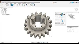
Step 6: Geometry Selection
In ProSolids WireEDM, the machining process is done through a combination of methods to define machinable features:
- Interactively created features from 2-dimensional and 3-dimensional geometry
- New features can be defined by adding new 2 or 4 Axis features interactively. Using this method, you can define inside, outside, and open contour features.
Step 7: Create a Feature and Toolpath
In the ProSolids WireEDM Toolbar, or by right clicking EDM Plane, select Create 2Axis Feature. This will open the Geometry Selection window.
Step 8: Adjust Operation Parameters
Each operation contains machining parameters that affect how the toolpath is created and specific parameters that will be output to the NC program. These parameters can be edited before post-processing the part.
Step 9: Simulate Material Removal
ProSolids WireEDM provides the ability to simulate the tool path showing the tool movement and the resulting shape of the part. The Simulate Toolpath button will launch Predator Virtual CNC and import part information.
Step 10: Post Process Toolpaths
Post-processing is the final step in generating the NC program file. ProSolids WireEDM creates NC code for each toolpath in the order the operation appears in the operation tree and the Process order specified on the Posting tab in the EDM Settings dialog box.
Screenshots


Commands
| Ribbon/Toolbar Icon | Command | Command Description |
|---|---|---|

|
ProSolids Settings |
Opens the ProSolids Settings command to adjust add-in settings. |

|
EDM Settings |
Opens the EDM Settings dialog for editing machining settings |

|
Create 2Axis Feature |
Opens the geometry selection command for creating 2 Axis operations. |

|
Create 4Axis Feature |
Opens the geometry selection command for creating 4 Axis operations. |

|
Generate Toolpath |
Rebuilds and generates updated toolpath. |

|
Search Cutting Conditions |
Opens the search cutting conditions dialog. Not supported by all machines. |

|
Edit Conditions |
Allows for the editing of machine-specific cutting conditions data. Not supported by all machine types |

|
Post Process NC-Code |
Post process and generate NC-Code for the part. |

|
Edit NC-Code |
Open the NC output in a text editor for review or editing. |

|
Simulate Toolpath |
Launches Predator Virtual CNC for simulation of the part. |

|
Toggle Toolpath Display |
Toggles the visibility of all EDM toolpaths. |

|
Machine Selection |
Opens the machine selection dialog for choosing the active machine. |

|
Stock Settings |
Opens the edit stock settings dialog. |

|
More Info |
Displays information about the add-in: version, subscription status, and active modules. |

|
Check for Updates |
Checks ProSolids for the latest version and provides a download if needed. |

|
Help |
Opens the help documentation |

|
Getting Started |
Opens a getting started page to provide quick access to guides and helpful resources. |
Installation/Uninstallation
Install:
- For detailed instructions, refer to our Installation Guide.
- On the downloads page, you can download ProSolids Wire EDM, the Installation Guide, and Predator Virtual CNC
- If using Predator Virtual CNC simulation, run that installer after ProSolids Wire EDM.
Uninstall:
- You can unload the add-in without uninstalling it by clicking the "Stop" button when the add-in is selected in the list box of the "Scripts and Add-Ins" dialog.
- Unchecking "Run on Startup" will stop the add-in in future sessions of Fusion.
- You can uninstall it just as you would uninstall any other application on your computer.
Activation:
In “C:\ProgramData\ProSolids\License”, double-click on the *.WibuCmLIF file.
Select the license and click on License Upgrade and follow the prompts to ‘create license request’. (*.WibuCmRaC)
Go to https://www.prosolids.com/dashboard/license-activation and fill out the form with the request file.
An activation file will be sent once the request has been verified (*WibuCmRaU). Double-click or drag it into the CodeMeter Control Center.
Finally, open ‘Process’ in the menu bar and select ‘Update Time Certificates’.
Additional Information
Note: Predator Virtual CNC is not included in the installed version downloaded from the app store.
For the latest version of ProSolids WireEDM and Predator Virtual CNC, installation guides, and other documents: https://www.prosolids.com/dashboard/downloads
Known Issues
Toolpath begins to unsynchronize – In some cases, with parts featuring very small faces or large U/V values, calculating the glue stop causes the upper and lower shapes to become out of sync. Work Around: Toggling the glue stop, changing its size, or moving the entry point can resolve this issue.
Inside/outside is identified incorrectly – In some cases, when the EDM setup is not in the same orientation as the model, the add-in will identify inside/outside features incorrectly. Work Around: Inside/Outside can be toggled from the data grid for each feature.
Geometry is not found or created – In some tapered and 4 Axis parts, the add-in fails to identify the correct geometry and displays no upper/lower loops.
Sections of the toolpath are missing – Cases with 4 Axis parts, splines will not get drawn into the toolpath, causing the toolpath to be incorrect. Work Around: Reversing the direction in the operation dialog or changing the entry point can resolve this.
Contact
Author/Company Information
Support Information
Bugs and issues can be reported here: https://www.prosolids.com/dashboard/bug-report
For additional support, email: randall@solidtogcode.com
Or go here: Contact Support - ProSolids Help
Version History
| Version Number | Version Description |
|---|---|
|
25.12.1213 |
Recent fixes include improvements to geometry selection, cases where dialogs become hidden, resource improvements, and a Getting Started Page. For more infomation, read all release notes here: https://www.prosolids.com/help/release-notes |
|
25.12.1202 |
Recent fixes include enhancements to geometry selection, Dark Theme Support, and Dialogs rendering off-screen. For more infomation, read all release notes here: https://www.prosolids.com/help/release-notes |
|
25.10.1185 |
Cummulative updates including fixes for: Start up and closing with multiple documents Setup Origin translation issues Face selection Issues 4 Axis message fix Delete All with only 1 Feature Enhancement including: Stop Code improvements Resource Update Entry Point Type in Selection command Browser Transparency Toggle |
|
25.08.1180 |
Initial Release for 2 and 4 Axis Support for English and German. |
