
TL Helmert Transformation
Win32 and 64, EnglishGeneral Usage Instructions
Start by defining a set of source/destination point pairs on the screen which will be used to compute a Helmert transformation.
(TLHelmertNew command)
Carefully examine the output information produced and pay particular attention to the list of residuals to make sure there are no outliers.
(Note: with a small number of observations identifying possible outliers might be difficult)
The Helmert transformation will compute values for the 7 parameters such that the error function value is minimized. The error function is defined as the sum of squared distances between the transformed source point set and the destination point set. In an ideal case, this number will be zero, resulting in a perfect match i.e. the source point set will exactly match the destination point set after transformation.
Once the transformation is computed it is automatically set as active/current and can be immediately used to transform Autodesk® AutoCAD® drawing entities using the TLHelmertTransformEntities command.
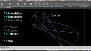
The app allows any combination of parameters to be turned on or off. For example, you may want to prevent rotation along the X and Y axes by turning off the Rx and Ry transformation parameters, resulting in a 5-parameter Helmert transformation. This can be accomplished by issuing the TLHelmertEdit command. Another common scenario is to disallow scaling by forcing a scale factor of 1.
The TLHelmertSave and TLHelmertLoad commands allow you to store/retrieve transformations to/from an XML file. Note that the TLHelmertLoad command will replace the current/active transformation.
If/when things don't go as expected the app provides two additional commands to help troubleshoot transformation issues:
The TLHelmertInfo command prints detailed information about the current/active transformation inside the standard AutoCAD command window and the TLHelmertVisualize command draws all those numbers on the screen in the form of AutoCAD entities to help better visualize how the source point set maps to the destination point set
For additional information please refer to the command section below.
Screenshots


Commands
| Ribbon/Toolbar Icon | Command | Command Description |
|---|---|---|

|
TLHelmertNew |
Computes a new 7-parameter Helmert transformation by identifying sets of common points and making it a current/active transformation for other commands. The user is asked to select source/destination point pairs on the screen. Source/destination point names can also be provided at this stage. Note that point names are supported for documentation purposes only and serve no other purpose. There is no hard limit on the number of points used to define the transformation. |

|
TLHelmertEdit |
Allows the user to selectively turn on/off individual parameters of the active transformation. The 7 parameters are: Tx: Translation/movement along the X axis is allowed/disallowed Ty: Translation/movement along the Y axis is allowed/disallowed Tz: Translation/movement along the Z axis is allowed/disallowed Rx: Rotation about the X axis is allowed/disallowed Ry: Rotation about the Y axis is allowed/disallowed Rz: Rotation about the Z axis is allowed/disallowed Scaling: Scaling is allowed or the scale factor is set to 1 if the setting is turned off Additionally, the transformation direction can be reversed by turning the IsReversed toggle on. |

|
TLHelmertLoad |
Loads a Helmert transformation from an XML file and sets it as current/active. |

|
TLHelmertInfo |
Displays detailed information about the current/active Helmert transformation: - Date - Time - User - Transformation parameters. - Error function value (EFV) / Square root of the EFV. - Average error per point. - Residuals list. - Source point matrix. - Destination point matrix. - AutoCAD transformation matrix. |

|
TLHelmertVisualize |
Draws a group of acad entities showing how the source point set maps to the destination point set: - Source point set is visualized as a closed 3dpline passing through all points - Destination point set is visualized as a closed 3dpolyline passing through all points - Transformed source point set is visualized as a green closed 3dpolyline passing through all points. Color is cyan if transformation is reversed - Source and destination point names are visualized as mtext objects - Source to transformed source point sets are visualized as 3d lines connecting each pair of points - Residuals/errors are visualized as red 3d lines connecting each pair of transformed source / destination points |

|
TLHelmertTransformEntities |
Transforms a user-selected set of acad entities using the active transformation Note that the command may fail if any of the selected entities are on a locked layer or do not support matrix transformation. |

|
TLHelmertTransformationActivate |
Activates the TL Helmert App with the Autodesk App Store. An active internet connection is required. Once activated the app can be used offline. This command is not available in the ribbon and needs to be manually typed in at the AutoCAD command prompt. |
Installation/Uninstallation
The installer that ran when you downloaded this app/plug-in from Autodesk App Store will start installing the app/plug-in. OR, simply double-click the downloaded installer to install the app/plugin. You may need to restart the Autodesk product to activate the app/plug-in. To uninstall this plug-in, exit the Autodesk product if you are currently running it, simply rerun the installer, and select the "Uninstall" button. OR, click Control Panel > Programs > Programs and Features (Windows 7/8.1/10/11) and uninstall as you would any other application from your system.
Once installation is complete launch your Autodesk product and make sure you're online and logged into your Autodesk account. Run the TLHelmertTransformationActivate command to activate the app. Once activated the app can be used offline.
Additional Information
Known Issues
The TLHelmertTransformEntities command may fail in certain cases:
- When all or some of the selected objects are on a locked layer.
- If/when objects are locked, such as locked cogo points in Autodesk® Civil 3D®.
Contact
Author/Company Information
Support Information
For questions/comments/suggestions/bug reports etc please send an email to Todor.Latev@gmail.com.
Version History
| Version Number | Version Description |
|---|---|
|
2022.11.19.1 |
Added 2024 support. |
|
2021.09.11.1 |
Added 2023 support. |
|
2019.4.10 |
Added 2022 support |
|
2019.4.10.1 |
Initial release. |
