
Layout Maker
Win64, EnglishGeneral Usage Instructions
1. Understanding what you want
Before starting App, it's better to spend a small amount of time to answer:
Target Paper size: which paper size will your document be printed on?
Paper drawing scale: which scale best fit your needs?
2. (Optional) Prepare a Title block
A Title block can be drawn at any scale, by any unit.
However, it should contains an outer boundary (by lines, polylines...) that exactly describe physical paper edges
3. (Optional) Prepare a Template layout
A typical template layout includes:
One viewport: Viewport scale should be suitable with target drawing scale. For example:
Model unit = meter, Paper unit = millimeter, Target drawing scale = 1/200 then
Viewport custom scale = 1/200 : (1mm /1m) = 5
One Title block: Title block should be manually scaled so that it's boundary fit paper edge
Plot settings: Printer, paper, Plot area, Plot style... should be set
(optional) Other Text, Leader, Legend block...
If you need to combine 2 or more viewports in a sheet, all viewports must be pre-arranged in one Layout template. Each Viewport may have a different custom scale.
Run the App:
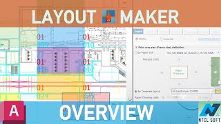
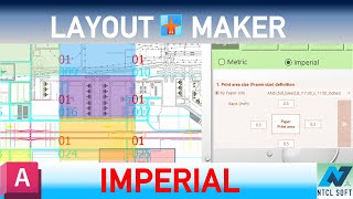
4. Define print area in Model space
a. Define print area size (Frame size) by one of two ways:
by Paper size and Margins or
by a Template layout
b. (Optional) Match each Frame Group number with a Viewport in Template layout
c. (Optional) Choose an active Frame Group number. Size and scale of the Viewport corresponding to that number will be used to calculate print area size in Model space
d. (Optional) Modify Frame overlap value if you want 2 nearby drawing to overlap each other. This value only takes effect if Frames are automatically inserted along an alignment
e. Manually insert Frames into Model space: you need to pick an insertion point, choose a rotation angle for each Frame. Frames' order number is automatically increased.
f. (Optional) Provide start station and end station values to auto insert frame from start to end station of and alignment.
g. (Optional) Change Active Group number and repeat from a. to f. New Frames of new Group(s) will be created.
5. Create Layout(s) and Viewport(s)
1 Frame to 1 Layout: Create multi Layouts from Frames. Each Frame (or Frame set in case using multi-viewport-per-1-layout template) corresponds to a Layout. Viewport(s) in Layout will be automatically zoomed and rotated to fit corresponding Frame.
All Frames to 1 Layout: All Viewports created from Frames of active group are put into one Layout. If using multi-viewport-per-1-layout template then All Viewports created from paired Frame groups are put into one Layout.
1 Frame to 1 Drawing: Create drawings from Model Frames. Each drawing contains 1 Layout + 1 Viewport. Model objects are partially copied to new drawing.
Newly created layout may also contains:
Title block instance
Any non-Viewport objects exist in Template layout
Screenshots


Commands
| Ribbon/Toolbar Icon | Command | Command Description |
|---|---|---|

|
NTCL_LAMaker |
Batch create viewports, layouts, and separated drawings from rectangle print areas in Model space |
Installation/Uninstallation
The installer that ran when you downloaded this app/plug-in from the Autodesk App Store will start installing the app/plug-in. OR, simply double-click the downloaded installer to install the app/plugin. You may need to restart the Autodesk product to activate the app/plug-in. To uninstall this plug-in, exit the Autodesk product if you are currently running it, simply rerun the installer, and select the "Uninstall" button. OR, click Control Panel > Programs > Programs and Features (Windows 10/11) and uninstall as you would any other application from your system.
Additional Information
- App interfaces support 7 languages. However, progress messages in the status text box are in English.
- App is installed to %AppData% \Autodesk\ApplicationPlugins folder instead of %ProgramData%\Autodesk\ApplicationPlugins folder.
Known Issues
1. After exporting separated drawings, color of objects in parent drawing may change unexpectedly. Actually object color was not changed. This maybe a temporary display issue related to the graphics cache and GPU rendering. To fix this symptom, just switching to a Layout tab and then back to Model Space to force a graphics refresh, which restores the correct display. The object color and layer settings remain unchanged.
Contact
Author/Company Information
Support Information
For questions/comments/suggestions/bug reports etc. please send an email to NTCLApp1@gmail.com
For more information about the license, please visit: https://www.ntclsoft.com/home/license-registration-guide
Version History
| Version Number | Version Description |
|---|---|
|
1.0.8 |
Improvements: - Support AutoCAD 2027 and verticals - 8-language interface - Improve speed when changing interface language Bug fixes: - Fix a bug where a layout template with only one viewport does not work properly |
|
1.0.0 |
Initial version. |
